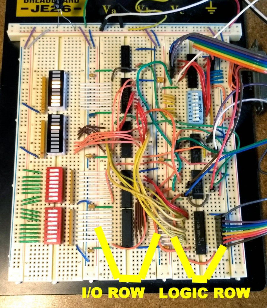
 (Breadboarded circuit) |
|
Video of the circuit executing sample code shown below |
There's nothing particularly groundbreaking about this project. A little Googling will give you dozens of example circuits for additonal digital I/O lines to a Z80, and this project isn't much different. We created this circuit to interface with the Z80 Microprocessor Kit we purchased (a very good product we highly recommend).
Our circuit has two 8-bit input ports and 2 8-bit output ports. For the two input ports, we used a 74LS245 which is pretty standard practise. The first output port is a 74LS273 which, again, is standard. The fun is in the second output where we chose to utilize a 74ALS996. Not only does the '996 act as an output like a '273, but it also provides readback, so you can read the status of its output lines. This gives the programmer the flexibility of not having to keep track of the status of the output lines themselves. The '996 also has a reset line which proved very useful for interfacing to our Z80 board.
Some fancy address decoding logic and bus isolation logic (another necessity to keep our circuit from interfering with the Z80 board's bus) complete the circuit.
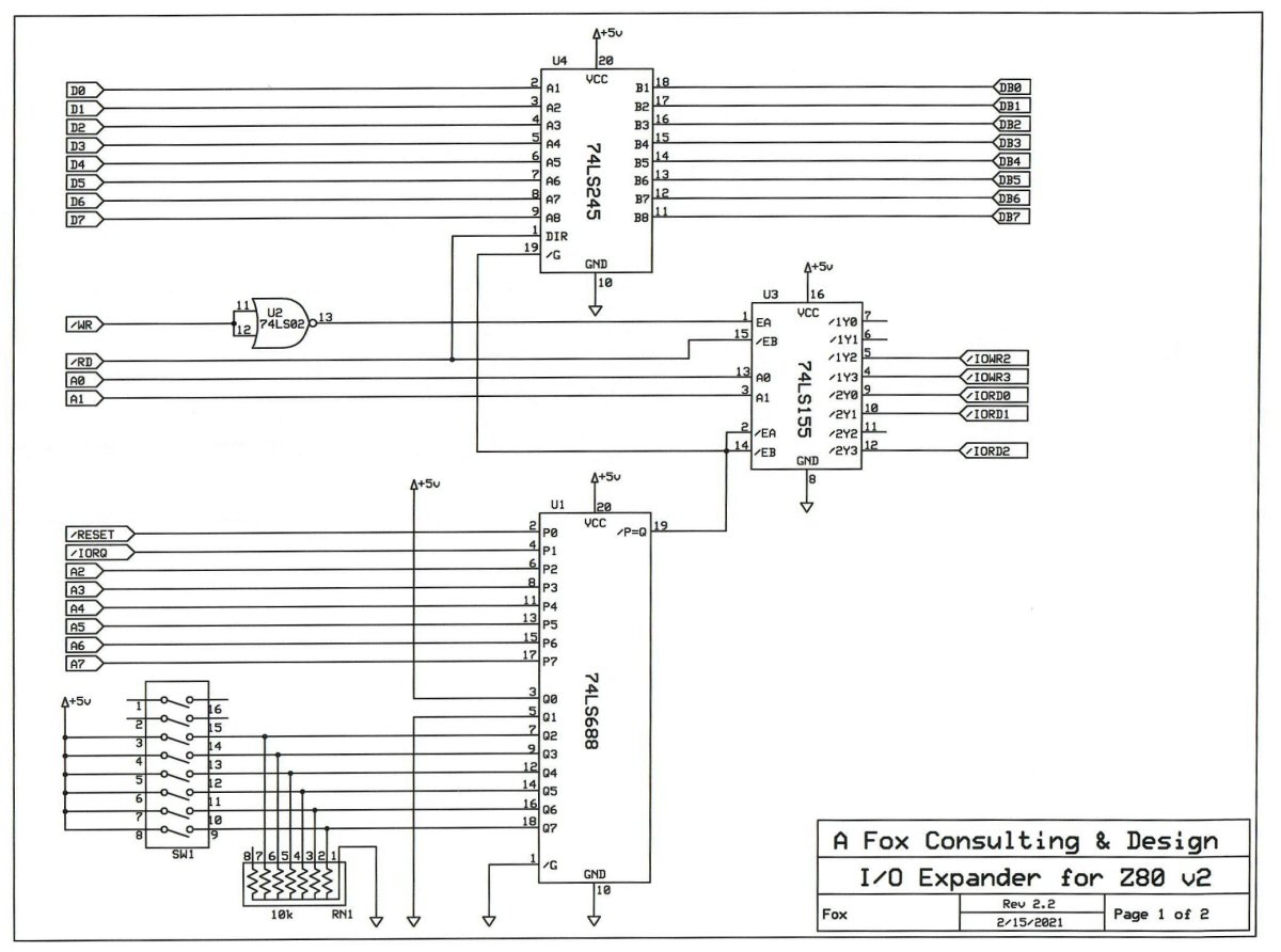 (Schematic for the logic row) |
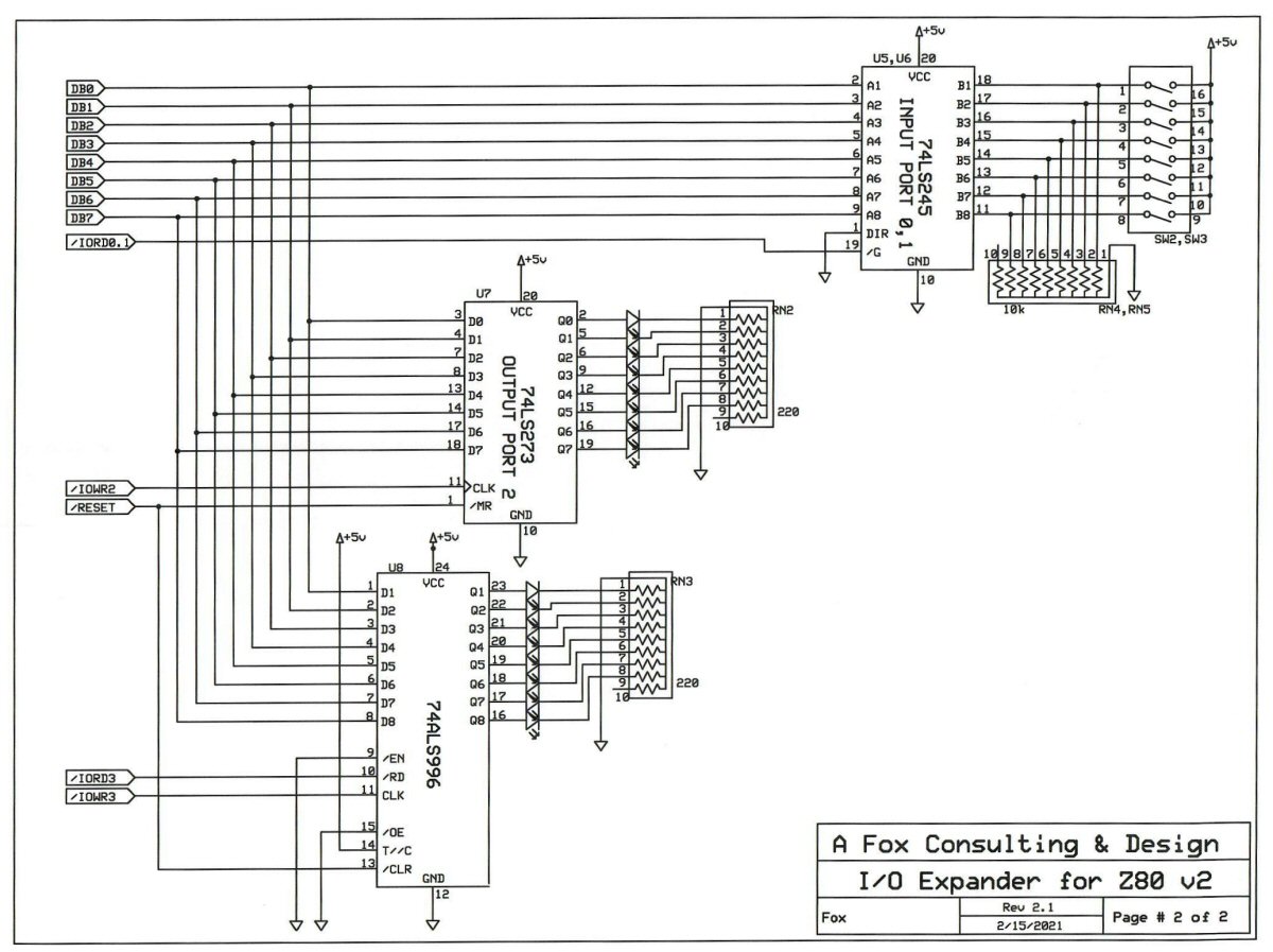 (Schematic for the I/O row) |
Sample assembly code demonstrating the circuit:
; Code for Z80
;
; Demonstration of I/O Expansion circuits for Z80 board
;   * 74LS245 is at I/O ports 0x10 and 0x11.
;   * 74LS273 is at I/O port 0x12.
;   * 74ALS996 is at I/O port 0x13.
;
; Demonstration #1 - Output Ports, 74LS273 vs 74ALS996
; Notice how the accumulator is used for the 74LS273
; while the 74ALS996 requires no register after initial setup.
;
                    .ORG 0x1800
                    LD      A,1
                    OUT     0x13,A
LOOP:               OUT     0x12,A
                    CALL    DELAY
                    RLC     A
                    PUSH    AF
                    IN      A,0x13
                    INC     A
                    OUT     0x13,A
                    POP     AF
                    JP      LOOP
DELAY:              LD      DE, 0xFFFF
                    LD      HL, 0x2000
LOOP2:              ADD     HL, DE
                    JR      C,LOOP2
                    RET
;
; Demonstration #2
; Simple echoing if input port values to output ports.
;
                    .ORG 0x1820
                    IN      A,0x10
                    OUT     0x12,A
                    IN      A,0x11
                    OUT     0x13,A
                    JP      0x1820